TIX Clock WIFI Hack
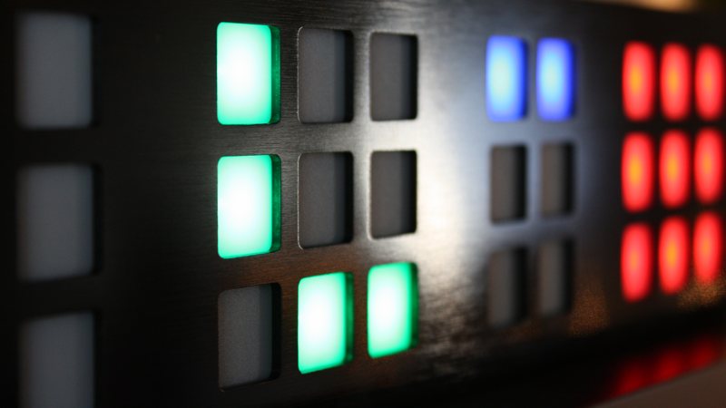
Years ago I got given a TIX clock. I like its stylish design and interesting way of representing time. Like a regular digital clock it tells time in hours and minutes, each broken up into tens and units. However instead of using characters it uses the corresponding number of lit up dots. To read the time you simply count the dots. It's slower to read, but a good conversation starter.
The problems with this clock are it has no battery backup and it's too bright at night. I wanted to plug it into a timer to turn it off while sleeping, but having to set it every morning was annoying. So I decided to add a WIFI connected micro-controller that will automatically set it when it's powered up.
The TIX is no longer for sale. Mine was discounted but originally they were quite expensive, so I suspect they didn't sell many and the company went under. There are instructions to make your own DIY TIX clock from scratch!
Electronics
I have no electronics background so this had to be a simple hack. I used a Spark Core (now updated and re-branded to Particle Photon) I had laying around which is an Arduino compatible micro-controller with WIFI on-board. Arduino is a simple electronics development platform, with a C-like programming language and a handful of pins that can be configured in various ways; input, output, PWM, I2C, serial, etc. Core (Photon) adds WIFI and remote programming to that.
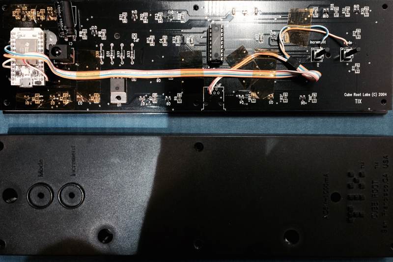
Opening up the clock I found a simple PCB with neatly laid out components, headers for (I assume) programming / test connectors, and even a socketed micro-controller. The micro-controller is a standard PIC chip which used to be popular before Arduino. This level of hackability / repairability is unusual in modern electronics and I would like to see more. I could have bought a PIC programmer board and reprogrammed the clock, but I saw little point as the factory firmware works well enough. There are more LEDs than outputs so they are multiplexed with PWM which would take some time to re-implement. According to a German blog post it's powered by a 6v AC (yes AC not DC!) wall-wart, and the mains frequency is used to keep time. I'm not sure if that's crazy or genius, but it does explain why there's no battery backup.
The clock has 2 buttons, mode and increment. It has to be the easiest clock I've ever set, it's a very nice UX. I decided to use the Spark Core so simulate these button presses to set the clock. A cheeky hack, but very simple.
It all needed just 4 wires. 2 for power, and 1 each per switch. The hardest part was figuring out how to "push" buttons digitally. I used a multimeter across a button and saw that when open there was 3v and when closed 0. That means pull-up resistors were being used to provide a steady reference voltage to the micro-controller's input when the switch is open (registers digitally as 1), and the other side of the switch is connected to ground so when pressed brings the pin voltage down to 0. Thus I needed my micro-controller to either "nothing" or ground the clock's micro-controller input.
A lot of searching confirmed this is possible (see coding section) so I soldered on the wires; no other components necessary. I taped the wires down with kapton / kopton / similar tape which is often used inside laptops for the same purpose as it's highly heat resistant. I actually have it for 3D printing. The Spark Core was small enough to fit in the case so you can't tell it's in there and is powered by the clock. I hot glued the Core in so I could remove it if I ever wanted it for other projects.
Coding
Intuitively the clock's micro-controller has its relevant 2 pins set to input, thus I should set my micro-controller's pins to output and send high and low to "push" the switches. DO NOT DO THIS! As the inputs have pull-up resistors they are expecting ground or nothing, not high (on / 3.3V). If you send high then you are in effect shorting 3.3v to ground through the micro-controller with little resistance; so it will blow up. The answer (without adding components) it to toggle the sending micro-controller between input and output low modes. The input part seems odd, but it makes the pin high impedance which is like not being connected. Output low grounds the pin as we want for a "press". Code snippet:
digitalWrite(pin_no, LOW);
pinMode(pin_no, OUTPUT); // the button "press"
delay(150); // give time for the other micro-controller to detect
pinMode(pin_no, INPUT); // "nothing" state
delay(150);
Daylight Savings
Particle has a library for time, which is automatically set when the Core connects to their cloud (made programming it very simple) but it doesn't handle daylight saving. In Europe DST begins on the last Sunday of March and ends on the last Sunday of October. I found a very simple method for calculating the day of clock change and wrapped it in a method. Note that Time.year() is from the Particle Std Lib so you might have to use an equivalent.
int offsetBST() {
    int startBST = 31 - (4 + 5 * Time.year() / 4) % 7;
    int endBST = 31 - (1 + 5 * Time.year() / 4) % 7;
    if (
        (Time.month() < 5 || Time.month() > 10) ||
        (Time.month() == 5 && Time.day() < startBST) ||
        (Time.month() == 5 && Time.day() >= endBST)
    ) return 0;
    return 1;
}
Result
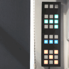
It works! I think it looks pretty cool while setting itself. There's a delay of a few seconds while it boots and connects to WIFI that I left out of the animation. The final time shown is 11:27. So far it's reliable, accurate, and much more convenient than manually setting it every morning. Having it adjust for BST makes it even more useful, especially on the groggy morning after a forgotten clock change; it could save some confusion.
Yes, sticking WIFI into a simple clock is overkill, but I had the Spark Core already and this seemed the easiest way to solve my problem, so why not?